Highway Engineering
Highway Planning, Surveys and Nepal Road Standards
PSC Subjective Note · Nepal Engineering Service (Civil), Second Paper
Scope of Nepal Road Standards
Nepal Road Standards -2027 (Second Revision 2070), in short called NRS-2070, shall apply to all Strategic Roads in rural areas being constructed within Nepal. For non-strategic (Local Roads) and urban roads separate standards shall be considered.
Road Classification
Roads in Nepal are classified as follows:
A. Administrative Classification
Administrative classification of roads is intended for assigning national importance and the level of government responsible for overall management and methods of financing. According to this classification, roads are classified into National Highways, Feeder Roads, District Roads and Urban Roads.
1. National Highways
National Highways are main roads connecting East to West and North to South of the nation. These serve directly the greater portion of longer-distance travel, provide a consistently higher level of service in terms of travel speeds, and bear inter-community mobility. These roads shall be the main arterial routes passing through the length and breadth of the country as a whole. They are designated by the letter H followed by a two-digit number.
2. Feeder Roads
Feeder Roads are important roads of a localized nature. These serve the community's wider interest and connect district headquarters, major economic centres and tourism centres to National Highways or other Feeder Roads. They are designated by the letter F followed by a three-digit number.
3. District Roads
District Roads are important roads within a district serving areas of production and markets, and connecting them with each other or with the main highways.
4. Urban Roads
Urban Roads are the roads serving within urban municipalities.
Under the organizational arrangements described in NRS-2070, the overall management of National Highways and Feeder Roads comes within the responsibility of the Department of Roads (DOR). These roads are collectively called Strategic Roads Network (SRN) roads.
District Roads and Urban Roads are managed by the Department of Local Infrastructure Development and Agricultural Roads (DOLIDAR). These roads are collectively called Local Roads Network (LRN) roads.
B. Technical / Functional Classification
For assigning various geometric and technical parameters for design, roads are categorized into the following classes:
Class I
Class I roads are the highest-standard roads, with divided carriageways and access control (expressways), and an ADT of 20,000 PCU or more in a 20-year perspective period. The design speed adopted for this class of roads in plain terrain is 120 km/h.
Class II
Class II roads are those with an ADT of 5,000–20,000 PCU in a 20-year perspective period. The design speed adopted for this class of roads in plain terrain is 100 km/h.
Class III
Class III roads are those with an ADT of 2,000–5,000 PCU in a 20-year perspective period. The design speed adopted for this class of roads in plain terrain is 80 km/h.
Class IV
Class IV roads are those with an ADT of less than 2,000 PCU in a 20-year perspective period.
Requirements of Highway Alignment
An ideal highway alignment should satisfy the following requirements, remembered as SESEC: Safe, Easy, Short, Economical and Comfort.
- Safe: The alignment should be safe during construction, operation and maintenance, particularly at slopes, embankments and cuttings.
- Easy: Availability of construction materials near the site makes construction easier. Easy gradients and curves also support vehicle operation.
- Short: The distance between the initial and final points should be as short as practicable to help reduce construction costs, subject to other alignment requirements.
- Economical: Consider construction, operation and maintenance costs together. A cheaper alignment to construct may have difficult gradients and higher operating costs, while easier gradients and curves may increase construction costs.
- Comfort: The alignment should provide comfort to drivers and passengers.
Factors Controlling Highway Alignment
Governmental Requirements
Road projects require substantial investment. The government should establish the need for the road and consider when, what, how and why it should be constructed.
Obligatory Points
Obligatory points influence the route and are divided into positive points, through which the alignment should pass, and negative points, which should be avoided.
Positive Obligatory Points
- Existing roads: Connecting the new road to the existing road network can reduce construction cost and improve connectivity.
- Intermediate towns: The alignment may need to connect a town between the starting and ending points, rather than following a direct route that bypasses it.
- Bridge sites or existing bridges: The road may need to be aligned to use a suitable bridge site or an existing bridge, with an appropriate approach alignment.
- Mountain passes: A pass may offer a suitable crossing where a road must cross a row of hills.
Negative Obligatory Points
- Valleys, ponds and marshy land, where practicable.
- Religious places and costly structures, to avoid social impacts, destruction and high compensation costs.
- Conservation areas, restricted zones and densely populated areas, where practicable.
Traffic and Geometric Design
The alignment should account for the type, volume and flow pattern of traffic. A preliminary estimate of the required number of lanes is:
Number of lanes ≈ Traffic volume / Capacity per lane
Use traffic volume and lane capacity for the same direction and time period, and round up to a whole number of lanes. Geometric factors such as curve radius, sight distance and gradient also influence the alignment.
Other Controlling Factors
- Geological conditions: Select stable hill slopes and consider soil and geological conditions.
- Construction materials and labour: Nearby sources can make construction easier and more economical.
- Economy: Compare construction, operation and maintenance costs when selecting the route.
- Drainage: Consider drainage needs and minimize the number of cross-drainage structures where practicable.
- Political and territorial considerations: Keep the alignment within the allocated territory and account for boundaries and restrictions.
- Monotony and safety: Long, straight alignments can lead to monotonous driving. Consider driver alertness and forgiving-road principles without introducing unnecessary or unsafe curves.
Special Considerations for Hill Roads
- Stability: Align the road along stable hillsides; excessive cutting and filling can affect slope stability.
- Drainage: Provide adequate drainage across the road and minimize cross-drainage structures where practicable.
- Geometric standards: Minimize steep gradients, hairpin bends and unnecessary rises and falls while meeting design requirements.
- Resisting length: Minimize ineffective rises and excessive falls along the route.
Engineering Surveys and Route Selection
Route Selection Process
After selecting the starting and ending points, define the region and progressively narrow the investigation from broad bands to a corridor, route strip and possible alignments. Typical widths are:
- Region — area containing the starting and ending points.
- Bands — approximately 8–16 km wide.
- Corridors — approximately 3–10 km wide.
- Route strips — approximately 1–1.5 km wide.
- Alignments — approximately 30–50 m wide.
Stages of Engineering Survey
- Map study
- Reconnaissance survey
- Preliminary survey
- Final location and detailed survey
1. Map Study
Topographical maps are studied to identify possible routes. The study helps locate alignments that avoid valleys, ponds and lakes, identify possible mountain passes across rows of hills, and find approximate bridge locations.
2. Reconnaissance Survey
Reconnaissance uses simple survey instruments and field observations to examine the possible routes. Information collected includes:
- Valleys, ponds, lakes and other features not shown on the map.
- Likely cross-drainage structures, high flood level (HFL) and natural ground level.
- Approximate gradients, lengths of gradients and circular curve radii.
- Soil types from field identification and observations of geological features.
- Sources of construction materials.
3. Preliminary Survey
The preliminary survey uses more detailed survey methods and instruments to collect physical information on topography, drainage and soil; compare proposed routes against the requirements of a good alignment; estimate earthwork quantities; and select the best alignment.
Conventional Approach
- Traverse: Run a traverse from the starting point to the endpoint using control points; primary and secondary traverses may be required.
- Levelling: Survey longitudinal and cross-sections along the proposed centre line to help estimate earthwork.
- Topographical features: Survey and plot natural and man-made features along the traverse and within a suitable width on either side.
- Drainage and hydrology: Study drainage and estimate the number of cross-drainage structures.
- Soil survey: Investigate earthwork, slope stability, materials, surface and subsurface drainage, and pavement requirements.
- Material survey: Locate sources of construction materials.
- Traffic survey: Collect traffic information for lane count, roadway width and pavement design.
- Final centre line: Determine the preferred centre line after the investigations and earthwork estimates.
Modern Rapid Approach
- Take aerial photographs with the required longitudinal and lateral overlaps.
- Examine the photographs under a stereoscope and select control points for establishing the traverse.
- Obtain spot levels and contours from stereo-pair observations.
- Use photo interpretation to investigate geological features, soil conditions and drainage requirements.
4. Final Location and Detailed Survey
Final location: Locate the centre line selected during the preliminary survey on the ground. Establish major and minor control points and drive centre pegs while checking geometric design criteria. Modify the location if necessary.
Detailed survey: Fix temporary bench marks (TBMs) at underpass and drainage structures. Take levels along the final centre line for vertical alignment, earthwork calculations and drainage details. Survey the soil profile to a depth of 1.5–3 m below ground level, and to twice the finished embankment height in the case of a high embankment. Complete the data needed to prepare plans, designs and project estimates.
Design Vehicle Dimensions and Axle Load
The maximum dimensions of vehicles and the maximum single axle load considered for the design of roads in Nepal are as follows:
| Parameter | Maximum value |
|---|---|
| Width | 2.50 m |
| Height | 4.75 m |
| Length | 18.00 m |
| Single axle load | 100 kN |
| SN | Vehicle type | Equivalency factor |
|---|---|---|
| 1 | Car, auto rickshaw, SUV, light van and pickup | 1.0 |
| 2 | Light (mini) truck, tractor, rickshaw | 1.5 |
| 3 | Truck, bus, minibus, tractor with trailer | 3.0 |
| 4 | Bicycle, motorcycle | 0.5 |
| 5 | Non-motorized carts | 6 |
Design Speed
The overall geometric design of a road is a function of design speed. Design speed is decided based on the importance of the road (road class) and the type of terrain. The design speeds to be adopted for various classes of roads are given below.
| Road class | Plain | Rolling | Mountainous | Steep |
|---|---|---|---|---|
| I | 120 | 100 | 80 | 60 |
| II | 100 | 80 | 60 | 40 |
| III | 80 | 60 | 40 | 30 |
| IV | 60 | 40 | 30 | 20 |
Design speed should be the guiding criterion for geometric design of the road. In very difficult terrain and unavoidable circumstances, design speed can be reduced to 75% of the values given in Table 3.
Stopping Distance
Stopping distance is the distance ahead needed by a driver to bring a vehicle to a complete stop before meeting a stationary object in its path.
Stopping distances for various speeds are given below.
| Speed (km/h) | Stopping distance (m) |
|---|---|
| 20 | 20 |
| 30 | 30 |
| 40 | 50 |
| 60 | 80 |
| 80 | 130 |
| 100 | 190 |
| 120 | 260 |
Overtaking Distance
Overtaking distance is the minimum distance that should be available to the driver to overtake another vehicle safely. Overtaking distances for various design speeds are given below.
| Speed (km/h) | Minimum overtaking distance (m) |
|---|---|
| 40 | 165 |
| 60 | 300 |
| 80 | 470 |
| 100 | 640 |
| 120 | 880 |
Hairpin Bends
In hilly areas it may become difficult to avoid bends where the direction of the road reverses. Design criteria for such bends, commonly known as hairpin bends, are given below.
| Parameter | Value |
|---|---|
| Minimum design speed | 20 km/h |
| Minimum radius of curvature | 15 m |
| Minimum length of transition curve | 15 m |
| Maximum longitudinal gradient | 4% |
| Maximum superelevation | 10% |
- A minimum distance of 60 m should be provided between successive bends of consecutive hairpin bends.
- At hairpin bends, it is preferable to pave the road to the full width of the roadway.
Set-Back Distance at Horizontal Curves
Adequate sight distance should be available across the inside of horizontal curves. The set-back distance is the distance from the road centre line within which obstructions should be cleared to provide the required visibility.
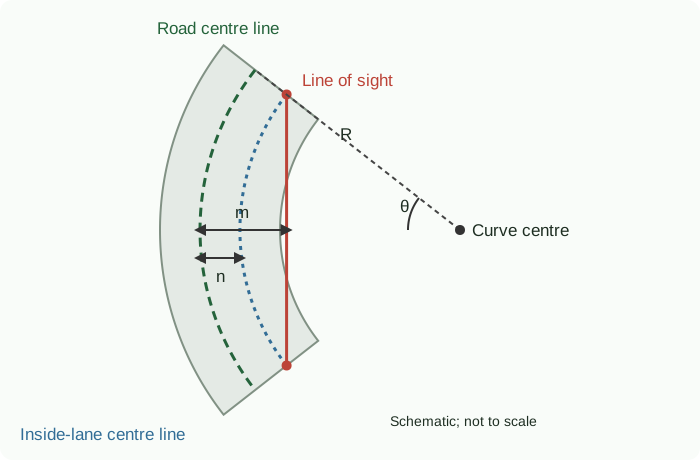
The minimum set-back distance is calculated as:
m = R − (R − n) cos θ
θ = S / [2(R − n)] radians
Where:
- m = minimum set-back distance to the sight obstruction, measured from the road centre line (m).
- R = radius at the road centre line (m).
- n = distance between the road centre line and the centre line of the inside lane (m).
- S = sight distance, measured along the road centre line (m).
- θ = angle in radians.
Maximum Longitudinal Gradients
- Vehicle operating cost is directly related to the longitudinal gradient, so gradients should be kept as small as possible.
- Gradients should be considered from the early stage of alignment fixing, as flattening them later can be difficult.
- The maximum gradient depends on the dynamic characteristics of commercial trucks, design speed and the maximum allowable speed reduction while climbing.
For a truck weight-to-power ratio of 120 kg/kW and a maximum speed reduction of 25 km/h below design speed, the maximum gradients are:
| Design speed (km/h) | Maximum gradient (%) |
|---|---|
| 20 | 12 |
| 30 | 10 |
| 40 | 9 |
| 60 | 7 |
| 80 | 6 |
| 100 | 5 |
| 120 | 4 |
The minimum longitudinal gradient for longitudinal drainage is 0.5%.
Grade Compensation
- The maximum longitudinal gradient shall be eased by 0.5% for each rise of 500 m above mean sea level.
- Due to the loss of tractive effort on curves, the gradient should be eased by the grade compensation calculated below.
- It is not necessary to compensate grades below 4%.
Grade compensation (%) = (30 + R) / R
Subject to a maximum of 75 / R (%), where R is the curve radius in metres.